


Frozen in time – Part 2
10th March 2014
In Part 2 of our special feature on the Grimsby Ice Factory, the Cooling Post takes a more in-depth look at the 80-year-old refrigeration system still contained within this historic building.
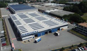
Once it was the largest factory of its kind in the world, supplying ice to one of the busiest fishing fleets in the largest fishing port in the world. Now boarded up and derelict for more than 20 years, the preservation of the Grimsby Ice Factory is the subject of a campaign by a determined group of locals, keen to save it and transform it into a major regional arts and leisure facility. Inside are a number of unique items of refrigeration equipment including four huge J&E Hall compressors installed as part of a major refit in 1931.
Based on new information from such sources as the National Archives and Grace’s Guides we have pieced together more information on how the refrigeration system operated.
This is an extract from a video by Martyn Bullock filmed in the sumer of 1990 and just days before the Grimsby Ice Factory finally closed its doors. The J&E Hall compressors shown still reside within the derelict factory. (It should be noted that there are a couple of errors in the documentary: the installation of the compressors was carried out in 1931 and the fifth compressor was not added until the early 1950s. Copies of the full 28-minute documentary are available and can be purchased here at a cost of £10.00.
The 1930s marked a distinct growth in the use of electricity in preference to steam in industrial manufacturing in the UK. The Electricity Supply Act of 1925, created the Central Electricity Board (CEB) and, in turn, the National Grid. This linked power stations for the first time and also encouraged investment in the construction of further power stations. By 1936, about 80% of the available electricity supply in the UK was used in industry.
Thirty years after opening, the Grimsby Ice Factory was still reliant upon steam-driven compressors. Although the refrigeration system had been expanded in line with increases in ice production, continuing demands for ice meant the Ice Factory was faced with the need to considerably increase output in the existing space.
The decision was taken to scrap the steam plant, ammonia compressors and equipment and replace them with modern high revolution electrically driven compressors, and to modify and update the cooling surfaces in the tanks and the brine and ammonia circulation. The removal of the steam boilers and the steam engines would also free up valuable extra space for ice production.

There were a limited number of companies equipped to undertake a project of this size. J&E Hall was one of the few.
Pioneers
J & E Hall has a history that few companies anywhere can match, let alone in the field of refrigeration. While the company did not become involved in refrigeration until the 1880s, the origins of the business go back to 1785 when John Hall began a one-man workshop at Dartford in the UK. During the early part of the 19th century J& E Hall was best known for manufacturing steam engines and gun carriages.
In 1886 J&E Halls’ cold air machine was being used to provide direct cooling for the preservation of provisions at sea and three years later the company installed a two-stage carbon dioxide compressor for a frozen meat store at London’s Smithfield Market. By the early 1920s J&E Hall had become established as a major player in refrigeration and had installed more than half of the world’s marine cargo refrigeration. On land, in food storage, brewing and other processing industries, J&E Hall progressed to be a world leader, from developing the cold-air machine, through the ammonia, CO2 and methyl chloride eras to the use of fluorocarbons.


High speed
The Grimsby Ice Factory installation was based around J&E Hall’s “high speed” ammonia compressors. Introduced in 1922 in response to a demand for faster running compressors, these vertical enclosed machines initially operated at speeds from 250-400rpm which, according to Harry Miller’s 1985 history of the company, Halls of Dartford, was very fast by standards of the time. Within 10 years the speed had been increased to 500rpm. They were initially designed by George Charles Hodson, J&E Hall’s chief designer. These machines, some of which were the largest ever built by the company, became widely used in breweries and other specialised industrial applications including four 80-year-old examples which still reside within the decaying ice factory.

The ice is made in cans of light sheet metal, which are immersed in tanks of cold brine until frozen solid. The cans are then lifted out and dipped in hot water for a few minutes, to thaw a thin film and free the ice, so that it can be tipped out of the can. Originally this hot water was provided by taking steam from the boilers but this supply is no longer available. Instead the heat of compression of the ammonia is utilised.
Hot gas from the compressor A is passed to the cooler B. Water was circulated through this cooler and used in the thawing tanks.
The cooled gas passed on to an oil separator C, from which any oil which may have been carried over by the gas was drained back into the crankcase of the compressor.
The gas then went to the condenser D and was liquified. The liquid gas then flowed into the separator F, where the level was maintained by a float valve H.
The liquid gas was drawn off by the pump G and forced through the coils of the brine tank.
The refrigerant evaporates and is returned to the compressor via the separator. The object of the separator was, of course, to prevent any partially evaporated liquid from finding its way into the compressor.
The circulating water for the cooler B flowed down to the thawing tank K and overflowed to the sump L where it was returned to the cooler by the pump M.
The atmospheric cooler J was provided as back-up for use in the event of high demand when very little was being passed through the thawing tank, causing the temperature of the cooling water to rise. It was reported that this was seldom called into action. There was, however, a small oil-fired boiler installed with the J&E Hall system (using parts from the dismantled economiser) that could be called upon to supply hot water in the event of the cooler being out of commission.
Twelve months after the installation was completed, The Engineer magazine was included amongst a delegation of engineers and customers who visited the site as guests of the Grimsby Ice Company, J&E Hall and Manchester-based Metropolitan-Vickers, who supplied the electrical machinery.
In its subsequent report the magazine described how all the steam-driven Pontifex and Linde ammonia compressors had been removed to make way for the four J&E Hall four-cylinder machines operating at a speed of 250rpm. These 16.5in dia, 15in stroke machines stand 11ft high, are each over 24ft long and were capable of producing pressures from 100-180psi.
The new compressors occupied roughly the same space as the 2oo ton steam-driven Linde machine installed in 1910, as is indicated by the dotted outline of the old equipment in the diagram from The Engineer at the top of the page.
Describing the compressors, The Engineer report describes the incorporation of a safety head, held down by powerful springs, being capable of lifting and easing the pressure if the cylinder was subjected to excessive pressure due through liquid ammonia finding its way in. “The lubrication of the bearings is effected through ducts drilled in the crank shaft and the connecting rods,” it says. “That is to say, oil is supplied under pressure from the oil pump. The oil finds its way to the crank pin and gudgeon in turn.
“We were interested to observe that the maker’s practice is to be chary in the cutting of oil grooves in the brasses and that such as are made are more or less circumferential with a slight helical tendency,” it added.

Above, right: Two Sulzer multi-stage pumps driven by 32hp motors at the floor level were employed to deliver water from the 175ft deep boreholes into a tank on the roof.
Oil trap
The oil did not appear to need appreciable renovation but some of the oil was inevitably carried away with the compressed gas. This oil was entrapped in the oil separator and led back to the compressor.
The Engineer observed: “It is naturally under the same pressure as the compressed gas and were a free passage allowed for it between the separator and the crank case, the latter would be liable to receive the delivery pressure, while compressed gas might be passed around the machine. So there is arranged a trapping device driven off the crank shaft.” 
The oil trap was described as a plug cock with a blind port, arranged in the return oil circuit and driven quite slowly by a worm gear (see drawing right). When the port faced the inlet for the return oil it was free to take a charge of oil, which at the next half revolution was passed to the crankcase; but there was never any through connection between the two sides of the plug cock.
“In the event of there being no oil return,” said The Engineer, “the utmost high pressure gas which can be by-passed is that contained in the blind port of the cock.”
A substantial flywheel, seen in all the photographs of the compressors, was interposed between the compressor and its motor to counter the inevitable cyclic variation in the speed of the compressor. This is said to have reduced the variation to about 1 in 350 and no distress was said to have been experienced by the motors and electric mains even when all the machines were running.
Circulating system
There is a diagram of the circulating system for one of the tanks reproduced in the booklet 1,100 tons Ice Plant and is reproduced here. Apologies for the fact that it is quite difficult to read but according to the description the remaining tanks were arranged in the same way, being fed from the same liquid main and the dry saturated ammonia being returned to the compressor by way of the same suction main.
 The liquid ammonia, instead of being fed directly to the evaporator coils was led into the liquid separating vessel. A motor-driven ammonia liquid pump circulated the ammonia through the evaporator coils, from which it was returned to the liquid separator. The liquid fell to the bottom of the vessel to be re-circulated by the pump and the dry gas was drawn off from the upper part of the vessel through the suction main by the compressors.
A constant liquid level was maintained by means of the float regulation valve which was fitted external to the separator and allowed just sufficient liquid to enter to compensate for that evaporated in the coils and drawn off in the form of gas by the compressor.
The operators said that in practice the load on all of the tanks, and consequently the brine temperature, was continually varying, owing to demands for ice being made irregularly on the various parts of the factory. It was found that this method of control dealt satisfactorily with the irregular conditions of operation without the aid of manual regulation.
The previous system used steam from the boilers to heat the cans to release the ice. This, they say, was considerable and was of course an entire loss. In the new installation the heat interchanger used the superheat from the discharge ammonia gas before it passes to the oil separator to heat the thawing water. The thawing water was pumped throught the cooler to each of the thawing tanks which were located on different levels and in different parts of the factory. It was then led to a sump tank and recirculated through the shell and tube cooler.
As the thawing process was not continuous a means was provided to dissipate the heat from this interchanger during the periods when no thawing was in progress. A set of atmospheric cooler coils was provided alongside the ammonia condenser coils which were cooled by the same dock water circulation when the thawing tanks were not in operation. The thawing water was automatically diverted to this cooler.
All four compressors were coupled to the one suction and one delivery main. The liquid from all condenser sections was also brought into one main from which branches were taken to the float valves on each of the liquid separator vessels.
Electric motors
As related in Part 1, each of the compressors was driven by a 600hp Metro-Vick synchronous induction motor designed for a 0.9 leading power factor. The supply from the local mains was 3-phase, 50 cycle at 6300V. The main motors were controlled by motor-operated liquid starters fitted with short-circuiting switches.
A variety of automatic arrangements were said to have been provided for safeguarding the operation of the plant, including one in which the compressors were all shut down by a combination of Bourdon tube and mercury contacts in the event that the pressure in the ammonia delivery pipe exceeded a safe limit. The safety measures were a wise move as there is calculated to have been around 100 tons of ammonia in circulation in the plant.
The booklet, 1,100 tons Ice Plant describes the extensive use of “electric welding” in the place of flanges for the ammonia pipe lines, which were of varying diameters, the maximum being 16in for the main suction and delivery pipes.

Amongst the archives the Cooling Post has uncovered the original typewritten manuscript which attributes the original work to F A Willcox DSc and C M Brain – both employees of J&E Hall.
Dr Frank Ainsworth Willcox, in particular, was a very significant figure in the early years of J&E Hall. In fact, he joined the company specifically to carry out trials on Hall’s first ammonia refrigeration compressors and went on to have a long and distinguished career with the company, also becoming president of the Institute of Refrigeration from 1935/6.
Charles Maurice Brain, although presumably a young man at the time, is also believed to have been an influential figure, becoming J&E Hall’s chief engineer. He also served as IoR president from 1961-63.
The reason for the change of authorship is open to speculation but within the text of the original manuscript it does state that the changes to the Ice Factory were on the recommendation of F A Fleming.
The condensers
The condensers for converting the compressed ammonia gas into liquid were arranged on the roof of the factory, some 60ft above the dock level and comprised simple hairpin banks of steel pipe over which the dock water was trickled, so that there was a certain amount of evaporative cooling effect.
The Engineer observed that the trickle of water was provided by a longitudinal slit in the top face of the horizontal distributing pipe and that the incidence of the distribution was effected by driving wooden wedges into this slit where water was not wanted.
It also noted that dock water was liable to leave a heavy deposit in the trays beneath that collect the return water. These condensers must have created a considerable load on the roof of the buildings.
This huge array consisted of 12in bore Staffordshire iron pipes in 34 stacks, 54 pipes high – a total run of 44,200ft, or well over eight miles. The circulating water was provided by three Mather and Platt centrifugal pumps, each of 108,000 gal/hr capacity and driven by 50hp motors.
Water supply
The supply of pure water for conversion into ice came from two 175ft deep, 12in diameter bore holes beneath the engine room.
Two Sulzer submerged multi-stage pumps driven by 32hp motors at the floor level delivered the water into a tank on the roof. The water was supplied to the freezing tanks by a system of troughing at the ends of the brine tanks. The trough ran right across the tank and were divided up into a number of compartments corresponding to the number of cans in the row. Water was poured into the trough and overflowed from one compartment into the next, so that each contained the correct amount for filling one can. Connected with the bottom of each compartment was a flexible pipe, which could be raised to prevent the outlet of water, or lowered to fill the can beneath.
 The cans were supported in light frameworks which ran on rollers on the sides of the tank and were propelled forward by screw-operated pushers after they were filled. These pushers were electrically-driven and had automatic arrangements that reversed and drew back the screw as soon as a stroke had been completed. The next row of cans then pushed forward those which has already been filled and started along the tank.
It is said to have taken about 27 hours for a row of cans to pass from one end to the other. The brine in the tank was chilled by ammonia coils that were arranged behind a partition in the side of the tank and the brine circulated by means of propeller pumps to ensure a free interchange of heat between it and the fresh water in the cans.
The frozen cans were lifted out, row by row, at the delivery end of the tank by an electric crane and transferred to the thawing tank which was just wide enough to take one row. As soon as they had thawed enough to free the ice they were lifted again and put in a cradle which tipped over and propelled the cakes of ice on to the floor. The cans were then picked up again by the crane and returned to the other end of the tank for refilling and a repetition of the process.
The crane was operated by a man walking along beneath who had push-button control of the gear that advanced the cans in the process of freezing. In all there were six freezing tanks containing 6606 cans of 2cwt and 3240 cans of 2.5cwt each.
According to The Engineer, the ice was produced in rectangular slabs of about 2cwt each and was picked up by elevators that delivered it to the top end of a chute that ran down to the trawler berths at the dock. There were said to have been several loading stations and at each there was a crusher to breaks up the slabs into a convenient size for packing into the ship’s hold. There were also two crushers in the factory which were used for supplying ice in barrels for distant delivery.

Electrical supply
There were said to be three electrical feeders to the factory arranged on a ring main. In order to ensure continuity of supply, the power was taken from the Grimsby generating station and also from sub-stations on Freeman St and Riby Street. In preparation of the inevitable electrification of the docks, a new sub-station was also established at the factory with panels to provide the necessary additional distribution facilities.
The metal-clad switchgear in the sub station was by Reyrolles of Hepburn on Tyne and the switches for the compressor motors formed part of this board. Two main transformers of 500kVA capacity, oil-filled, three-phase, 50 periods, 6300/415V, indoor core type were installed. Each was said to have been capable of supplying a total ultimate load of approximately 700hp of motors, the rating having been based on a load factor of 60%, allowing for standby services and intermittent operation. The transformers were designed for parallel operation if required, but were normally intended each for full-load duty, one always being available as spare.
The lighting voltage was kept down to 110V AC due to the damp conditions of the ice factory. For this service two 20kVA oil-filled indoor core type transformers were used.
One compressor was installed and used for all the initial tests. It appears that this was the machine on the extreme left of the illustration at the top of the page.
In March 1932, a trial was conducted over a period of 10 days, using this compressor and Nos 1, 2 and 5 ice tanks. Throughout the whole period ice was lifted at a constant rate during the 24 hours, the brine temperatures consequently remaining steady. The trial was divided into two periods: a) One compressor working on tanks 1, 2 and 5 b) One compressor working on tanks 1 and 2 The results obtained during these two periods were:
Trial periods a) b)
Evaporation temperature ºF 13 5
Condensation temperature ºF 79 69
Tons of ice produced/24hr 403 342
Total kW/ton – ice tipped on the
platform, inc ice handling,
crushing, etc 30.6 32.0
Total kW/ton – ice tipped on the
platform, for compressors and
auxiliaries 28.3 28
kW/ton – ice tipped on
platform, compressor only 25.8 26.1
These figures were taken when the rate of ice lifting was constant and are claimed give the true performance of the plant. The table below taken from the company’s logs and included in the published booklet 1,100 tons Ice Plant provides a record of working over an eight week period. However, owing to the electrical installation not being complete, the authors comment that was only possible to give the total kW consumption and not split the figure up, as is the case with the test results when specially calibrated integrating wattmeters were fitted in the circuit of every electric motor in operation.

Frederick Fleming
A major driving force behind the changes made to the refrigeration system in 1931 appears to have been the Grimsby Ice Factory’s general manager Frederick A Fleming.
Born in Newport-on-Tay, just across the river from Dundee, Fleming was awarded the MBE in 1920 for his contribution to the war effort as manager of the Grimsby National Shell Factory. Production had ended there in 1918 and when the honour was made he was already general manager of the Grimsby Ice Factory.
He joined the Institution of Mechanical Engineers on the last day of 1919 and joined the Institute of Refrigeration (then the British Association of Refrigeration) in 1921. An attendee at the annual dinner in London, he is also listed as a member of the executive council of the institute in 1935.
He lived in a modest four-bedroom terrace House in Mill Road, Cleethorpes until his death in May 1941 at the age of 67.
It is not known when he left the employ of the Ice Factory but his funeral was attended by the chairman and directors of the Grimsby Ice Company and a number of the office staff, suggesting he may have still been working there until shortly before his death.
At his funeral Frederick Fleming was lauded as a great engineer and one of the oldest and most active members of the Grimsby Rotary Club. He was also described as “a man of striking personality, who did not hesitate to express his convictions, being at times so direct as to be almost pugnacious, though one always felt that he was sincere.”
All qualities which were probably called upon during the revamping of the Ice Factory.
Later developments
There was at least one further major expansion and upgrade of the refrigeration equipment within the Ice Factory. A further J&E Hall 4-cylinder high speed ammonia compressor was installed separate to the other four machines in the early 1950s. A further borehole, this one nearly twice the size of the existing two at 350ft deep and 21in dia, is also reported to have been dug at around the same time. At some stage the roof-top condensers were also removed to be replaced by six, 16ft-high vertical condensers.
This equipment also remains within the factory but at the moment the Cooling Post is unaware whether the Reyrolles switchgear survived and it seems likely that some of the other 1930s equipment, like the borehole pumps, may well have been replaced and updated before the factory closed.

Post-war also saw a period of change for J&E Hall. Sadly, the Dartford factory is no more. Ironically, a supermarket now stands on the site but the company does still maintain its headquarters offices and some R&d facilities in the town.
In 1959 the company merged with air conditioning pioneers Thermotank to become Hall-Thermotank. The merged company was subsequently acquired by APV in 1976 and renamed APV Hall.
In 1995 AAF McQuay International, by then part of the Malaysian OYL group, purchased the refrigeration and freezer interests of APV in the UK. It was a move that was to see the re-instatement of the J&E Hall name.
In 1996 the company gained another new owner. This time it was the world’s largest air conditioning manufacturer Daikin who in buying OYL also added the world’s oldest refrigeration company to its portfolio.
The Cooling Post would like to thank a number of companies and individuals for their help in putting this information together including Graeme Bassett of GGIFT, Guy Hundy, Chris Lester and the IoR and anyone else we may have missed.
Coming soon: The Grimsby Ice Factory’s Age of Steam