


Leak detection in complex VRF systems
30th December 2013There is a growing acceptance that refrigerant leaks have both a direct effect through the release of global warming gases and an indirect effect through system inefficiencies brought on by incorrectly charged systems. The growing popularity of VRF systems has prompted many manufacturers to incorporate embedded leak detection systems.  In this edited version of a paper presented at the recent Institute of Refrigeration conference, Graham Wright (right) of Daikin UK looks at how current leak detection processes have evolved within VRF systems and expands on some of the technology currently being used.
The containment of F-gases is a legal requirement in Europe and management of leaks and refrigerant handling is an audited process. However, there is evidence that an incorrectly charged HFC system can emit more CO2 due to inefficiencies of the system.
One of the factors VRF manufacturers have focused upon to improve system reliability are embedded leak detection systems. Low pressure switches to detect a lack of refrigerant within a system have now largely been by more complex equipment that monitors the whole system and shuts the system down in the event of a leak.
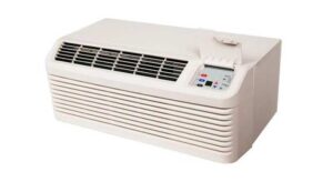
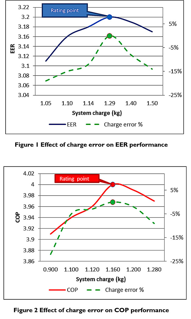
Studies by Daikin in Japan suggest that under or over charged systems can have a significant impact on efficiency. This can be seen with test carried out on a 3kW hi-wall system with 6m pipe run.
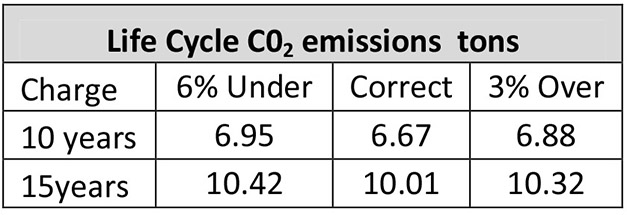
The results indicate that even a small error in charging a system or a system with a small leak would directly affect the system’s predicted efficiency and, therefore, increase its CO2 emissions. The differences may not be significant on this system but similar results on larger systems could have an important impact on the expected performance of the equipment.
VRF systems have grown in popularity since their first introduction in 1985. In Europe the market was initially limited to combinations of systems of between 5-8 indoor units connected to one outdoor condensing unit. Market demands and technology changes have seen this grow to far larger systems. In Daikin’s case this can mean combinations of up to 64 indoor units connected to three outdoor units (in one group) with up to 1,000m of pipe work.
There are approximately 16,000 outdoor units sold into the UK each year and sales are expected to continue to increase. The indoor to outdoor unit ratio is fairly constant at around 6:1 suggesting that the majority of systems are applied to smaller applications or multiple systems on one site.
With this number of systems sales it is important to ensure that installations are carried out correctly and any issues with the refrigerant containment of a system must be detected and remedied as soon as it’s detected. This process starts at the design/installation of a system where the pipework runs and locations are recommended to be kept a short as possible.
Once an installation is completed the pipework is triple evacuated and pressure tested in the normal way.
On Daikin VRV equipment the start-up process begins with the commissioning engineers checking the pipework schematic with the actual site installation. The actual charge for the system is then calculated to ensure that the correct amount of refrigerant is on site and to act as a double check for the auto-charge process.
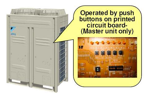 Before charging the system is powered up and the internal controls set via PCB inputs. This opens all the electronic valves and expansion device in the indoor units and enables the system to be evacuated. The same settings are used in refrigerant recovery mode.
To understand the auto charging routine of this type of equipment we first of all have to recognise that the volume of refrigerant change varies depending on the system load, mode of operation and ambient conditions. The excess charge is stored in the outdoor unit within the refrigerant regulator which, in effect, is a sealed pressure vessel.
This device manages the liquid gas separation and can store a large proportion of the total system refrigerant charge. The system is also monitored by several pressure/temperature transducers which enable the heating, cooling, and heat recovery to be closely monitored. Every indoor unit and its refrigerant flow control devices also monitor the cooling/ heating effect that the system is producing. This enables the entire installation to monitor its status intelligently, both during the charging process and during normal operation.
The system is run through a sequence that starts with auto charge. The internal and external conditions along with the discharge and suction pressures within the system are detected and constantly monitored while the auto charge process is underway and adds refrigerant accordingly.
When auto charge is complete a learning process is run through for 2-3 hours followed by a full running commission check carried out by software embedded within the outdoor unit that monitors pressures, temperatures from indoor and outdoor units. Once complete the system is able to monitor its charge automatically and basic F-gas checking can be undertaken using the base data created during this process.
F-gas Leak checking
Currently a service technician will have to initiate the process but future developments will allow for this test to be carried out automatically when the system is in an “off” mode. In essence, once started the test runs the system in cooling mode for 20-40 minutes.
The results are given to the technician in the following format and the routine can detect a loss of refrigerant larger than 500g. The results are compared with the initial data from the self-charge process.
Whilst this is not perfect it is very unlikely that a service technician could detect a similar leak during a normal service of a system unless of course they find it as part of a pipework inspection which should be still carried out.
System monitoring
Monitoring of these systems has become an intrinsic part of the operational life of these systems. Even if the building management options are not connected the outdoor units are constantly testing to ensure that the operational refrigerant pressure and temperatures are kept within normal parameters, depending on the mode of operation and the conditions the system is working in. Should these be exceeded the system will report an alert.
Once five such alerts have been recorded the system initiates a pump down of refrigerant into the outdoor unit’s refrigerant regulator and reports the fault to system controls as a leak detected. In the case of a catastrophic failure a normal LP switch will shut the system down immediately.
Other prognostic services which allow the complete system to be actively monitored are now becoming more common place. This enables all faults and especially changes in operating conditions of refrigerant circuits to be spotted almost immediately.
Systems such as this help service technicians identify a change in refrigerant charge but they do not offer building inhabitants any form of indication of a possible danger of a leak within their room or office. While designers seem to be well aware of the issue surrounding the safety aspects of EN378 and concentration rates it is not unusual for these to be forgotten or misunderstood by building operators and maintenance engineers.
As a result, several manufactures now offer guidance and systems that directly notify occupants of an affected area. These alarm systems are connected to the main BMS and the embedded controls within these types of systems that use standard HFC refrigerants such as R410A.
This is an edited version of a paper presented at the Institute of Refrigeration Conference in London on December 2, 2013. Further information from the Institute of Refrigeration at www.ior.org.uk